PVC-U DEEP WELL
CASING&SCREEN PIPES
Up to 500 m Depth

U-PVC DEEP WELL CASING & SCREEN PIPES
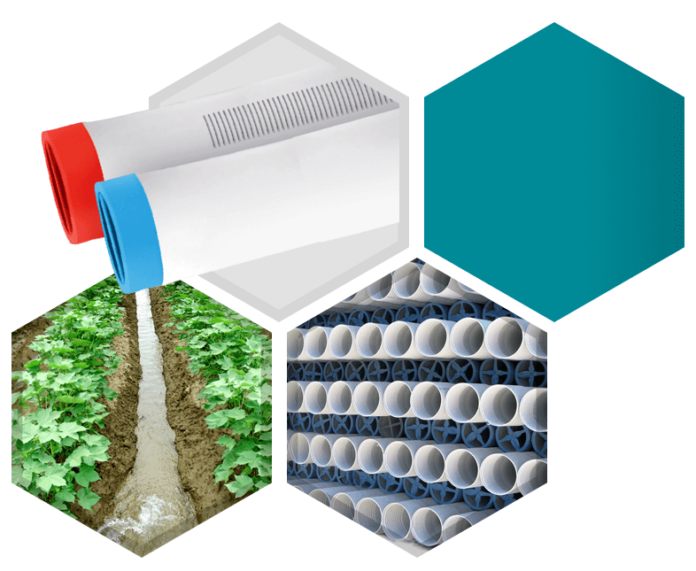
 In the deep wells that are dig to benefit from underground waters, deep well pipes are used. All over the world instead of steel pipes, after the widespread of the usage of filter and closed deep well pipes that are produced from PVC, specific standards that are determined physical properties of the pipes and filter slots are issued.
In case of failure of deep well pipes, it is hard to reach defective area, it is even impossible.
Our deep well pipes are manufactured according to TS 11794 standard. Reduction, the spur that is installed to the end of the pipe, centering spring, belted pipe clamping switch, swivel maneuver head, and pipe holders that will hold the pipes at the well head are produced by International quality standarts.
With years of experience and the notion of work which gives priority to meticulous and superior quality of all production provide opportunities the filter and closed pipes to be used safely both in domestic and foreign. The filter slots have a width of 2mm according to TS11794 standard.
CONNECTION METHOD AND THREAD PROPERTIES

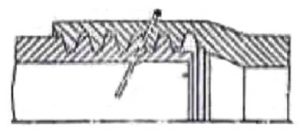
Our PVC deep well filter and closed pipes are produced with a male pipe thread at a spigot end and a female pipe thread at the socket end. As seen figure; the pipes’ threads are trapeze so they enable safe and easy connection. Also, there is no need to any additional materials. This feature is both economic and time-saving. Because during the installation, there is no need some labors welding operations.etc
OTHER PROPERTIES
During the landing to wells, even the pipes weight create axial tension, both the pipe and the thread system has a power to meet these loads. Our deep well pipes is very lighter than steel pipes.
This feature provides much convenience in handling and installation. With the effect of rust and corrosion, steel deep well pipes spoil within 15 years depending on the structure of soil and water. In this case, it is necessary to be opened a new well. Our deep well pipes resist to corrosion and chemicals such as acids and bases because they were made of PVC and they also last at least 50 years. And it can leads continuity and economy.
While the well is hammered, in case of the gravels collocate to each other and become a square (figure a), the ratio of the area that the water passes through them is 21.46%.
However it is not possible that the gravels stay as square, they stay as triangle. (Figure b) In this case, the proportion of the area that the water passes through does not exceed 9.31%. This area varies according to the pipe’s diameter and wall thickness in the PVC deep well pipes and they are between 9.5% -11.
POINTS TO CONSIDER
- While loading and carrying, don’t hit the ground and especially protect the threads which are at the ends.
- If the pipes have to be held for a while before used, they should be stored on chock and covered with a fabric to protect them against sunlight.
- The protective caps on the male ends should never be removed until the pipes are ready to be used.
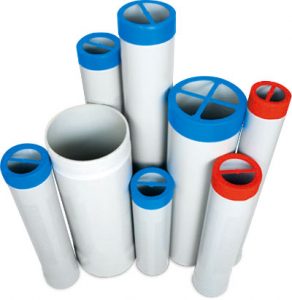
- Use and filter pipes according to written depth (until 100 m 0-100; until 300 m 101-300).
- The diameter of the pump used must match the internal diameter of the pipe.
- No liquid substance, such as lubricating grease should be used in order to create an easy pipe installation.
- An adhesive material should never be applied to the surface of the pipe’ thread because it melts the pipe and deforms the pipe’ thread.
- In installation, appropriate tools must be utilized such as a belt wrench. Don’t use chain wrench or pipe key.
- For vertical position in the well, maximum every 8 m centering spring should be used.
- Especially make sure that there is one closed pipe at the bottom.
- If the pipe resists to moves freely down into the well, well mud should be inserted inside the pipe with a gun or bucket. While doing this, the pipe must not be damaged.
- If the pipe is stuck in the well, the pipe shouldn’t be hammered. It should be taken out and lowered back into the well. In spite of all these, if the pipe does not move down, the well should be hollowed out once again with a drill and then the pipe is pushed down the well.
- Once the pipe touches the bottom of the well, it should be pulled up at least 10cm from the ground and suspended. Until the process of paving with pebbles finishes, the pipe must be held straight in vertical position.
- A sheet iron pipe must be installed on top of the well and outside the furnished drilling PVC pipe and the pump must be positioned on the sheet iron pipe.
- Pebbles should be shovel evenly, continuously, and orderly along the perimeter of the furnished pipe. This way, the pipe can stay vertical.
- Especially in silt land, pebbles must be prevented from creating a bridge. If the silt comes from the well continuously, but the level of pebble does not decrease then there can be a bridge. Take emergency precautions rub in pebble, otherwise your well collapses.

DEEP WELL PIPES DIMENSIONS AND TOLERANCING
Up to 100 m Depth (On pipes articles BLACK)
| Outer Diameter | Thickness | Inner Diameter | External Dimensions | Weight (Kg) (Closed) | |||||
| Pipe | Mufin | ||||||||
| mm | inch | mm (max) | mm | Tolerans (mm) | (Min) mm | mm x m | 2 mt | 3 mt | 4 mt |
| 113 | 4″ | 123 | 5,0 | +0,70 / -0,00 | 101,6 | TR 113X6 | 5,25 | 7,75 | 10,33 |
| 125 | 5″ | 136 | 5,5 | +0,80 / -0,00 | 111,4 | TR 125X6 | 6,55 | 9,60 | 12,65 |
| 140 | 5 1/2″ | 153 | 6,5 | +0,90 / -0,00 | 125,3 | TR 140X6 | 8,40 | 12,45 | 16,50 |
| 175 | 6 5/8″ | 192 | 8,0 | +1,00 / -0,00 | 157,0 | TR 175X6 | 12,85 | 19,05 | 25,25 |
| 200 | 5″ | 220 | 9,0 | +1,20 / -0,00 | 179,6 | TR 200X6 | 16,50 | 24,50 | 32,50 |
| 225 | 8 5/8″ | 247 | 10,0 | +1,20 / -0,00 | 202,6 | TR 225X6 | 20,70 | 30,70 | 40,70 |
| 250 | 9″ | 274 | 11,0 | +1,25 / -0,00 | 228,0 | TR 250X6 | 26,53 | 39,3 | 52,65 |
| 280 | 10 3/4″ | 301 | 12,5 | +1,40 / -0,00 | 252,2 | TR 280X12 | 32,37 | 47,90 | 63,43 |
| 330 | 12 3/4″ | 356 | 14,5 | +1,70 / -0,00 | 297,6 | TR 330X12 | 44,30 | 65,55 | 86,80 |
| 400 | 15 1/2″ | 434 | 18,0 | +2,00 / -0,00 | 360,0 | TR 400X12 | 64,74 | 95,79 | 126,83 |
Up to 300 m Depth (On pipes articles RED)
| Outer Diameter | Thickness | Inner Diameter | External Dimensions | Weight (Kg) (Closed) | |||||
| Pipe | Mufin | ||||||||
| mm | inch | mm (max) | mm | Tolerans (mm) | (Min) mm | mm x m | 2 mt | 3 mt | 4 mt |
| 140 | 5 1/2″ | 157 | 8,0 | +1,00 / -0,00 | 125,3 | TR 140X6 | 10,15 | 15,05 | 19,95 |
| 175 | 6 5/8″ | 197 | 10,8 | +1,20 / -0,00 | 157,0 | TR 175X6 | 15,80 | 23,50 | 31,20 |
| 200 | 5″ | 225 | 11,5 | +1,40 / -0,00 | 179,6 | TR 200X6 | 20,88 | 31,48 | 41,28 |
| 225 | 8 5/8″ | 254 | 13,0 | +1,50 / -0,00 | 202,6 | TR 225X6 | 26,36 | 39,10 | 51,84 |
| 250 | 9″ | 274 | 14,5 | +1,25 / -0,00 | 221,0 | TR 250X6 | 35,58 | 49,73 | 65,87 |
| 280 | 10 3/4″ | 310 | 16,0 | +1,80 / -0,00 | 252,2 | TR 280X12 | 40,80 | 60,35 | 79,90 |
| 330 | 12 3/4″ | 366 | 19,0 | +2,20 / -0,00 | 297,6 | TR 330X12 | 56,85 | 84,15 | 111,45 |
| 400 | 15 5/8″ | 445 | 22,7 | +2,20 / -0,00 | 360,0 | TR 400X12 | 82,80 | 122,08 | 161,66 |
Up to 500 m Depth (On pipes articles GREEN)
| Outer Diameter | Thickness | Inner Diameter | External Dimensions | Weight (Kg) (Closed) | |||||
| Pipe | Mufin | ||||||||
| mm | inch | mm (max) | mm | Tolerans (mm) | (Min) mm | mm x m | 2 mt | 3 mt | 4 mt |
| 140 | 5 1/2″ | 163 | 10,4 | +1,25 / -0,00 | 116,7 | TR 140X6 | 12,90 | 19,15 | 25,40 |
| 175 | 6 5/8″ | 204 | 13,0 | +1,40 / -0,00 | 148,2 | TR 175X6 | 20,20 | 29,73 | 39,44 |
| 200 | 8″ | 234 | 14,5 | +1,60 / -0,00 | 171,0 | TR 200X6 | 28,00 | 42,00 | 56,00 |
